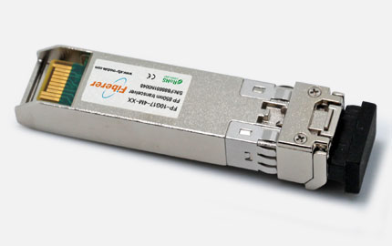
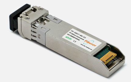
Fiberers F6901 10Gb/s Enhanced Small Form Factor Pluggable SFP+ transceivers are designed for use in 10-Gigabit Ethernet links up to 10Km over Single Mode Fiber. They are compliant with SFF-8431, SFF-8432 and IEEE 802.3 aq 10GBASE-LRM. Digital diagnostics functions are available via a 2-wire serial interface, as specified in SFF-8472.
Product Features - 10Gbps SFP+ Optical Transceiver 1310nm
Data-rate of 10.3125Gbps operation
1310nm DFB laser and PIN photo detector
Optical interface compliant to IEEE 802.3ae
Compliant with SFP+ MSA and SFF-8472 with duplex LC receptacle
Maximum link length of 10Km on 9/125um SMF
All-metal housing for superior EMI performance
+3.3V single power supply and Hot Pluggable
Operating case temperature: 0 to +70C
Low power consumption
Applications - 10Gbps SFP+ Optical Transceiver 1310nm
10GBASE-LR at 10.3125Gbps Ethernet
10GBASE-LW at 9.953Gbps Ethernet
10GE Storage, 8G Fiber Channel
Other optical transmission systems
Standard - 10Gbps SFP+ Optical Transceiver 1310nm
Compliant with SFF-8431 and SFF-8432
Compliant with SFF-8472 Rev 10.2
Compliant with IEEE 802.3ae 10GBASE-LR and 10GBASE-LW
RoHS Compliant
Description - 10Gbps SFP+ Optical Transceiver 1310nm
This 1310nm DFB 10Gigabit SFP+ transceiver is designed to transmit and receive optical data over 9/125 m single mode optical fiber single.
The SFP+ LR module electrical interface is compliant to SFI electrical specifications. The transmitter input and receiver output impedance is 100 Ohms differential. Data lines are internally AC coupled.
The module provides differential termination and reduce differential to common mode conversion for quality signal termination and low EMI. SFI typically operates over 200 mm of improved FR4 material or up to about 150 mm of standard FR4 with one connector.
Absolute Maximum Ratings
|
Parameter |
Symbol |
Min |
Max |
Unit |
|
Maximum Supply Voltage |
Vcc |
0 |
3.6 |
V |
|
Storage Temperature |
Ts |
0 |
70 |
C |
|
RX Input Average Power |
Pmax |
|
0 |
dBm |
|
Relative Humidity |
RH |
5 |
95 |
% |
Recommended Operating Conditions
|
Parameter |
Symbol |
Min |
Typical |
Max |
Unit |
|
Operating Case Temperature |
Standard Tc |
0 |
25 |
70 |
C |
|
Power Supply Voltage |
Vcc |
3.13 |
3.3 |
3.47 |
V |
|
Power Supply Current |
Icc |
|
|
260 |
mA |
|
Power Consumption |
|
|
600 |
800 |
mW |
|
Data Rate |
|
|
10.3125 |
|
Fbps |
Transmitter Optical and Electrical Characteristics
|
Parameter |
Symbol |
Min |
Typical |
Max |
Unit |
|
Centre Wavelength |
c |
1260 |
1310 |
1355 |
nm |
|
Side-Mode Suppression Ratio |
SMSR |
30 |
|
|
dB |
|
Average Output Power |
Pout |
-8.2 |
|
0.5 |
dBm |
|
Extinction Ratio |
ER |
3.5 |
|
|
dB |
|
Transmitter Dispersion Penalty |
TDP |
|
|
0 |
dB |
|
Relative Intensity Noise |
Rin |
|
|
-128(12dB reflection) |
dB/Hz |
|
Optical Return Loss Tolerance |
|
|
|
12 |
dB |
|
Optical Rise/Fall Time
(20%~80%) |
tr/tf |
0.03 |
|
|
ns |
|
Data Input Swing Differential |
VIN |
90 |
|
350 |
mV |
|
C common mode voltage tolerance |
|
15, |
|
|
|
Data Dependent Input Jitter |
DDJ |
|
|
0.1 |
UI |
|
Data Input Total Jitter |
TJ |
|
|
0.28 |
UI |
|
Input Differential Impedance |
ZIN |
90 |
100 |
110 |
|
|
Transmit Disable Input |
High |
VIH |
2.0 |
|
Vcc+0.3 |
V |
|
Low |
VIL |
0 |
|
0.8 |
V |
|
Transmit Enable Output |
High |
VOH |
2.4 |
|
Vcc+0.3 |
V |
|
Low |
VOL |
0 |
|
0.4 |
V |
Receiver Optical and Electrical Characteristics
|
Parameter |
Symbol |
Min |
Typical |
Max |
Unit |
|
Centre Wavelength |
c |
1260 |
1310 |
1355 |
nm |
|
Receiver Sensitivity |
Psens |
|
|
-14 |
dBm |
|
Receiver Overload |
Pin |
|
|
0.5 |
dBm |
|
LOS De-Assert |
LOSD |
|
|
-12 |
dBm |
|
LOS Assert |
LOSA |
-3, 0<, /SPAN><, , SPAN style="FO, NT-FAMILY: Arial; FONT-SIZE: 9pt" lang=EN-US> |
|
|
dBm |
|
LOS Hysteresis |
|
0.5 |
|
4 |
dB |
|
Stressed Sensitivity in OMA |
|
|
|
-10.3 |
dBm |
|
Receiver Reflectance |
Rrx |
|
|
-12 |
dB |
|
Data Output Swing Differential |
Vout |
300 |
|
850 |
mV |
|
Output Differential Impedance |
Zon |
90 |
100 |
110 |
|
|
LOS Output |
High |
VOH |
2.4 |
|
Vcc+0.3 |
V |
|
Low |
VOL |
0 |
|
0.4 |
V |
Diagnostics Specification
|
Parameter |
Range |
Unit |
Accuracy |
Calibration |
|
Temperature |
0 to 70 |
|
3 |
Internal / External |
|
Voltage |
3.0 to 3.6 |
V |
3% |
Internal / External |
|
Bias Current |
0 to 100 |
mA |
10% |
Internal / External |
|
TX Power |
-10 to 2 |
dBm |
3dB |
Internal / External |
|
RX Power |
-22 to 2 |
dBm |
3dB |
Internal / External |
Pin Definitions - 10Gbps SFP+ Optical Transceiver 1310nm
|
PIN |
Symbol |
Description |
Remarks |
|
1 |
VEET |
Transmitter ground (common with receiver ground) |
Circuit ground is isolated from chassis ground |
|
2 |
Tx_Fault |
Transmitter Fault. Not supported |
|
|
3 |
Tx_Disable |
Transmitter Disable. Laser output disable on high or open |
Disabled: TDIS>2V or open
Enabled: TDIS<0.8V |
|
4 |
SDA |
2-wire Serial Interface Data Line |
Should Be pulled up with 4.7k C 10k ohm on host board to a voltage between 2V and 3.6V |
|
5 |
SCL |
2-wire Serial Interface Clock Line |
|
6 |
MOD_ABS |
Module Absent. Grounded within the module. |
|
7 |
RS0 |
No connection required |
|
|
8 |
RX_LOS |
Loss of Signal indication. Logic 0 indicates normal operation |
LOS is open collector output |
|
9 |
RS1 |
No connection required |
|
|
10 |
VEER |
Receiver ground (common with transmitter ground) |
Circuit ground is isolated from chassis ground |
|
11 |
VEER |
Receiver ground (common with transmitter ground) |
|
12 |
RDC |
Receiver Inverted DATA out. AC coupled |
|
|
13 |
RD+ |
Receiver Non-inverted DATA out. AC coupled |
|
|
14 |
VEER |
Receiver ground (common with transmitter ground) |
Circuit ground is isolated from chassis ground |
|
15 |
VCCR |
Receiver power supply |
|
|
16 |
VCCT |
Transmitter power supply |
|
|
17 |
VEET |
Transmitter ground (common with receiver ground) |
Circuit ground is isolated from chassis ground |
|
18 |
TD+ |
Transmitter Non-Inverted DATA in. AC coupled |
|
|
19 |
TDC |
Transmitter Inverted DATA in. AC coupled |
|
,
|
20 |
VEET |
Transmitter ground (common with receiver ground) |
Circuit ground is isolated from chassis ground |
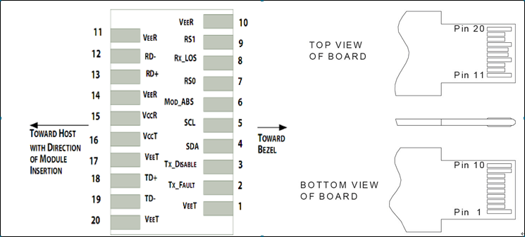
Diagram of Host Board Connector Block Pin Numbers and Names
SFP Module EEPROM Information. and Management
The SFP+ modules implement the 2-wire serial communication protocol as defined in the SFP -8472.
The serial ID information of the SFP+ modules and Digital Diagnostic Monitor parameters can be accessed through the I2C interface at address A0h and A2h. The memory is mapped in Table 1. Detailed ID information(A0h) is listed in Table 2. And the DDM specification at address A2h. For more details of the memory map and byte definitions, please refer to the SFF-8472, Digital Diagnostic Monitoring Interface for Optical Transceivers.
-632.jpg)
Digital Diagnostic Memory Map (Specific Data Field Descriptions)
|
Data Address |
Field Size (Bytes) |
Name of field |
Description of field |
|
BASE ID FIELDS |
|
0 |
1 |
Identifier |
Type of serial transceiver (03h=SFP) |
|
1 |
1 |
Ext. Identifier |
Extended identifier of type of serial transceiver(04h) |
|
2 |
1 |
Connector |
Code for connector type (07=LC) |
|
3-10 |
8 |
Transceiver |
Code for electronic compatibility or optical compatibility |
|
11 |
1 |
Encoding |
Code for serial encoding algorithm ( 64B/66B (06h)) |
|
12 |
1 |
BR, Nominal |
Nominal bit rate, units of 100 MBits/sec(67h) |
|
13 |
1 |
Reserved |
(0000h) |
|
14 |
1 |
Length(9um) - km |
Link length supported for 9/125 um fiber, units of km |
|
15 |
1 |
Length (um) |
Link length supported for 9/125 um fiber, units of 100 m |
|
16 |
1 |
Length (50um) |
Link length supported for 50/125 um fiber, units of 10 m |
|
17 |
1 |
Length (62.5um) |
Link length supported for 62.5/, 125 um fiber, units of 10 m |
|
18 |
1 |
Length (Copper) |
Link length supported for copper, units of meters |
|
19 |
1 |
Reserved |
|
|
20-35 |
16 |
Vendor name |
SFP transceiver vendor name (ASCII) |
|
36 |
1 |
Reserved |
|
|
37-39 |
3 |
Vendor OUI |
SFP transceiver vendor IEEE company ID |
|
40-55 |
16 |
Vendor PN |
Part number provided by SFP transceiver vendor (ASCII) |
|
56-59 |
4 |
Vendor rev |
Revision level for part number provided by vendor (ASCII) |
|
60-62 |
3 |
Reserved |
|
|
63 |
1 |
CC_BASE |
Check code for Base ID Fields (addresses 0 to 62) |
|
EXTENDED ID FIELDS |
|
64-65 |
2 |
Options |
Indicates which optional SFP signals are implemented (001Ah = LOS, TX_FAULT, TX_DISABLE all supported) |
|
66 |
1 |
BR, max |
Upper bit rate margin, units of % |
|
67 |
1 |
BR, min |
Lower bit rate margin, units of % |
|
68-83 |
16 |
Vendor SN |
Serial number provided by vendor (ASCII) |
|
84-91 |
8 |
Date code |
Vendors manufacturing date code |
|
92-94 |
3 |
Reserved |
|
|
95 |
1 |
CC_EXT |
Check code for the Extended ID Fields (addresses 64 to 94) |
|
VENDOR SPECIFIC ID FIELDS |
|
96-127 |
32 |
Read-only |
Vendor specific data, read only |
|
128-511 |
384 |
Reserved |
|
|
512-n |
|
|
Vendor specific |
EEPROM Serial ID Memory Contents (A0h)
SFP+ Host Board Schematic
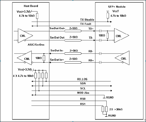
Diagram of SFP+ Host Board Schematic
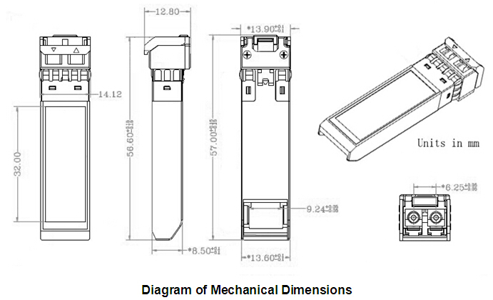
Mechanical Dimensions - 10Gbps SFP+ Optical Transceiver 1310nm
References
1. Specifications for Enhanced Small Form Factor Pluggable Module SFP+, SFF-8431, Rev 4.1, July 6,2009.
2. Improved Pluggable Formfactor,SFF-8432, Rev 4.2,Apr 18,2007
3. IEEE802.3ae C 2002
4. Diagnostic Monitoring Interface for Optical Transceivers SFF-8472, Rev 10.3, Dec 1,2007
 Loading...


 fiberer_engineer3


